Article No. VK-IND08
IND08 Detection of discontinuities
Analysis of applicability and performance of different discontinuity locating techniques of non-destructive testing with ultraound using a test block with different types of discontinuities (defects)
- Subject matter of the experiment
- Theoretical and practical aspects of the experiment
- Results
- Equipment
- Related Experiments
Using a test block with different types of discontinuities (defects), the applicability and performance of different discontinuity locating techniques of non-destructive testing with ultrasound are analysed and the choice of the correct locating technique for specific testing tasks is discussed.
Keywords: Ultrasonic echography, discontinuity, reflection, incidence angle, refraction angle, A-Scan, B-Scan, normal probe, angle beam probe, signal-to-noise ratio
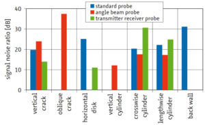
Different methods of locating and size determination are necessary depending on the type of discontinuity. In the experiment, a test block with idealised discontinuities is investigated with a normal probe, an angle beam probe and a transmitter-receiver probe (TR or dual-element probe). B-Scan images of the test block are recorded with each probe and analysed. In a second series of tests, the signal-to-noise ratio for the discontinuities found is determined with each probe. Based on the results, the detectability of the discontinuity types with the individual locating methods is evaluated and their selection is discussed as regards special test tasks of practical application.
The results summarised in the diagram show that different discontinuity types require differentiated locating methods. For example, small discontinuities can only be located by the analysis of the scattering signals with the transmitter-receiver probe. From the oblique crack, one can only receive an echo signal with the angle beam probe, and from the back wall only with the normal probe. In addition, the boundaries of the modelled discontinuities become clear. So in practice, a perpendicular crack will not be detectable with the normal probe or will be substantially more difficult to detect than the saw cut in the test block intended to model such a crack.
| Ord.no. | Description |
|---|---|
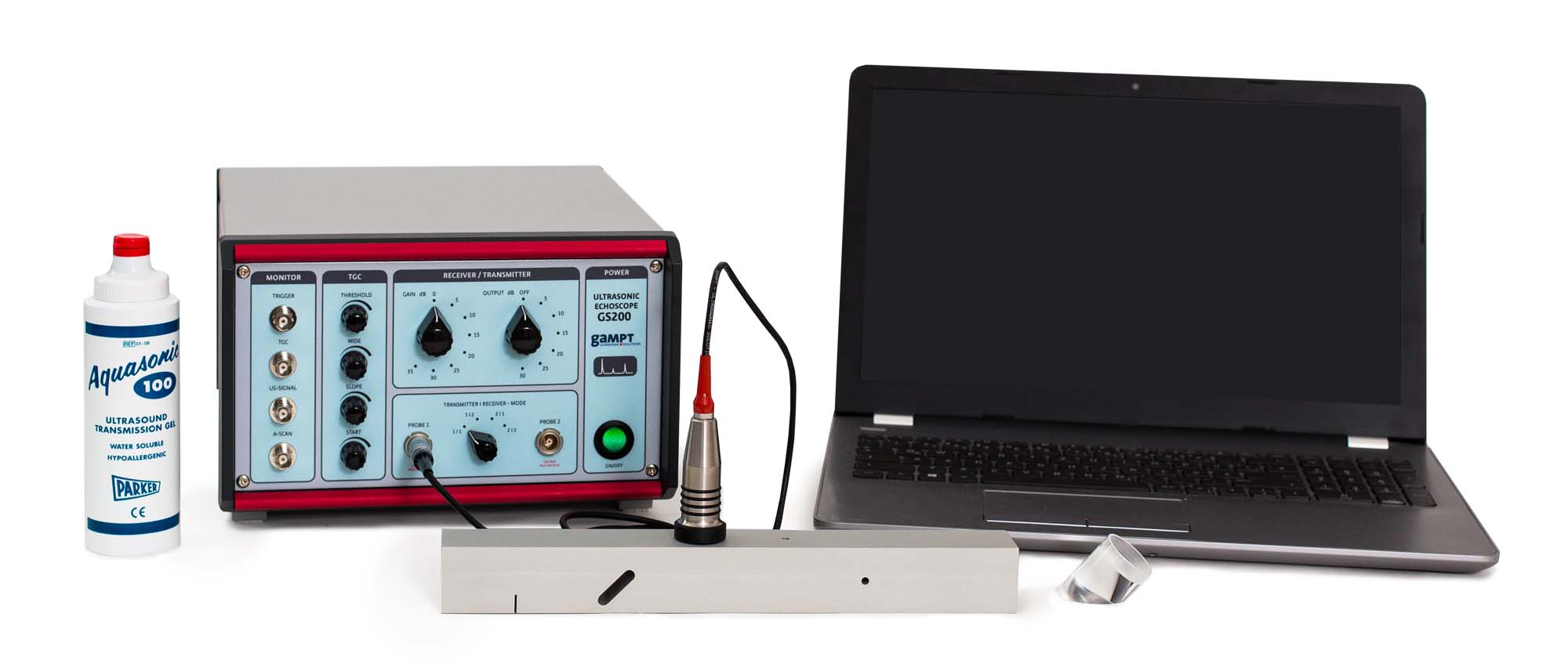
| 10400 | Ultrasonic echoscope GS200 |
| 10152 | 2 ultrasonic probes 2 MHz |
| 10234 | Angle beam wedge 38° |
| 10237 | Transceiver delay line (TOFD) |
| 10242 | Discontinuity test block |
| 70200 | Ultrasonic gel |
| PHY08 | Ultrasonic B-Scan |
| IND01 | Non-Destructive Testing (NDT) |
| IND06 | Angle beam testing |
| IND07 | Crack depth determination (TOFD)(TOFD) |

